Molecular orbital diagrams
This article provides a brief introduction to the creation of molecular orbital diagrams in LaTeX using the modiagram package. Readers are strongly encouraged to consult the modiagram package documentation which contains numerous helpful examples to demonstrate its many features—far more than we can address in this short article.
For information about the more traditional molecular structure diagrams see our documentation about chemistry formulae.
Introduction
Molecular diagrams are created using the modiagram package which you import to your document by adding the following line to its preamble:
\usepackage{modiagram}[\(\langle\)options\(\rangle\)]
The set of \(\langle\)options\(\rangle\) are listed, and demonstrated, in the package documentation.
To apply package \(\langle\)options\(\rangle\) globally you can
- set them when you load the package via
\usepackage{modiagram}[\(\langle\)options\(\rangle\)], or - use the setup command
\setmodiagram{\(\langle\)options\(\rangle\)}
MO diagrams are created using the modiagram environment, which supports local use of package \(\langle\)options\(\rangle\):
\begin{modiagram}[\(\langle\)options\(\rangle\)]
...
\end{modiagram}
The following example demonstrates a minimal modiagram environment without any using any \(\langle\)options\(\rangle\):
\documentclass{article}
\usepackage{modiagram}
\begin{document}

First example atoms:

\begin{modiagram}
\atom{left}{1s, 2s, 2p}
\end{modiagram}
\end{document}
Open this example in Overleaf.
This example produces the following output:
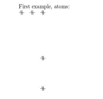
The basic command to draw MO diagrams is \atom which, as demonstrated in the example above, takes two arguments:
left: the alignment of the atom.1s, 2s, 2p: the energy sub-levels to be drawn. These can be further customized as you will learn in the next section.
Atoms
You can pass some extra information about the atomic orbitals to the command presented in the introductory example.
\documentclass{article}
\usepackage{modiagram}
\begin{document}

\begin{modiagram}
 \atom{right}{
    1s = { 0; pair} ,
    2s = { 1; pair} ,
    2p = {1.5; up, down }
 }

 \atom{left}{
    1s = { 0; pair} ,
    2s = { 1; pair} ,
    2p = {1.5; up, down }
 }
 \end{modiagram}
\end{document}
Open this example in Overleaf.
This example produces the following output:
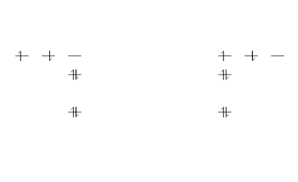
In this example, two identical atoms are drawn, left- and right-aligned respectively.
Following the style of the modiagram package documentation, the generic syntax to create atoms can be written as:
\atom[\(\langle\)name\(\rangle\)]{\(\langle\)left\(\rangle\)|\(\langle\)right\(\rangle\)}{\(\langle\)AO-spec\(\rangle\)}
where
- \(\langle\)
name\(\rangle\) is an optional name for the atom - \(\langle\)
left\(\rangle\) and \(\langle\)right\(\rangle\) determine the placement in the diagram - \(\langle\)
AO-spec\(\rangle\) is the specification of the Atomic Orbital.
The \(\langle\)AO-spec\(\rangle\) takes the general form
sub-level = {energy; specifications}
where
sub-levelcan be1s,2sor2penergyis the energy level, a number that determines the vertical spacing in the diagram. If omitted it is set to 0.specificationsis a comma-separated list of the spins of the electrons contained in each orbital. The possible values areup,down,pairand empty (only the semicolon is typed) for an empty orbital. If omitted it is set topair.
Here is a description of the commands used in the previous example:
1s = { 0; pair}. The sub-level1sis in the0energy level, the orbital contains two (paired) electrons.
2s = { 1; pair}. The sub-level2sdrawn in the1energy level, there are two electrons in this orbital.
2p = {1.5; up, down}. The sub-level2pdrawn in the energy level1.5, i.e. in the diagram the vertical spacing is set to 1.5; this sub-energy level has two electrons: one with spinupin the first orbital and another with spindownin the second orbital.
The same commands are repeated for the second atom on the right.
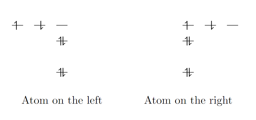
To display the (optional) name of an atom use a modiagram environment with the [names] option:
\documentclass{article}
\usepackage{modiagram}
\begin{document}
\begin{modiagram}[names]
 \atom[Atom on the right]{right}{
    1s = { 0; pair} ,
    2s = { 1; pair} ,
    2p = {1.5; up, down }
 }

 \atom[Atom on the left]{left}{
    1s = { 0; pair} ,
    2s = { 1; pair} ,
    2p = {1.5; up, down }
 }
\end{modiagram}
\end{document}
Open this example in Overleaf.
This example produces the following output:
Molecules
The syntax for molecules is very similar to that of the \atom and, in the style of the documentation, can be written as:
\molecule[\(\langle\)name\(\rangle\)]{\(\langle\)MO-spec\(\rangle\)}
where
- \(\langle\)
name\(\rangle\) is an optional caption of the molecule - \(\langle\)
MO-spec\(\rangle\) is the specification of the Molecular Orbital
The energy sub-levels 1s, 2s and 2p become 1sMO, 2sMO and 2pMO respectively. Here is a basic example:
\documentclass{article}
\usepackage{modiagram}
\begin{document}
\begin{modiagram}
 \atom{left}{1s}
 \atom{right}{1s={;up}}
 \molecule{
    1sMO={0.75;pair,up}
  }
\end{modiagram}
\end{document}
This example produces the following output:
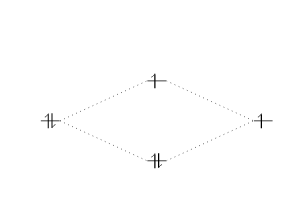
In the example above, the molecular orbital specification (\(\langle\)MO-spec\(\rangle\) ) is
1sMO={0.75;pair,up}
where
0.75is now the ratio (energy gain)/(energy loss).pair, upare the spins of the electrons in the bonding and anti-bonding molecular orbitals, respectively.
The next, slightly more elaborate, example should help you understand the syntax:
\documentclass{article}
\usepackage{modiagram}
\begin{document}
\begin{modiagram}
 \atom{left}{
      1s, 2s, 2p = {;pair,up,up}
  }
  \atom{right}{
      1s, 2s, 2p = {;pair,up,up}
  }
  \molecule{
      1sMO, 2sMO, 2pMO = {;pair,pair,pair,up,up}
  }
\end{modiagram}
\end{document}
This example produces the following output:
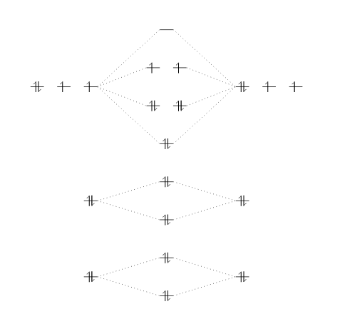
Three atoms are set on each side of the diagram and the corresponding molecule is in the middle.
Naming scheme
The following diagram is reproduced from the modiagram package documentation. It contains the names (labels) used for the orbitals, which are nodes in a tikzpicture and thus can be used in standard TikZ drawing commands within a modiagram environment.

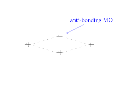
Here is an example using the name of the anti-bonding orbital 1sigma* for relative positioning.
\documentclass{article}
\usepackage{modiagram}
\begin{document}
\begin{modiagram}
 \atom{left}{1s}
 \atom{right}{1s={;up}}
 \molecule{
    1sMO={;pair,up}
 }
 \draw[<-,shorten <=8pt,shorten >=15pt,blue]
 (1sigma*) --++(2,1) node {anti-bonding MO};
\end{modiagram}
\end{document}
Open this example in Overleaf.
This example produces the following output:
Further reading
For more information see: